If you’ve ever looked into building your own PC, you may have seen that the two components most vital to the machine’s actual computation are its processor and memory. Any gamer or video editor giddy to describe the power of their rig to you will always base its tech-specs around measures of its processor’s speed and memory’s space. Even if you’ve never seen the inside of a computer, you’ve probably at least heard of the transistor, the basic building block of all computational components that has made it possible to build computers at the scales we see today. But if that’s where your knowledge on the matter of computer hardware stops, you may be left with many questions.
How do you go from simple electric circuits that do little more than power light bulbs to a designs that can save you from having to calculate your own taxes? What is the role that transistors play in this? On a fundamental level, how does it all work? These are the types of questions I would ask myself when I began my foray into the field of computing. In this post I want to gently outline the basic mechanics by which modern computers were conceived, primarily by covering the jump that took place between the simple circuit and the logic circuit. We’ll explore this by way of two principal concepts.
Storage & Manipulation
Like a car, a computer is a system. It is a group of connected components whose interactions achieve a greater function. While a car’s function is to convert fuel into motion, a computer’s function is to map one set of data to another by carrying out a defined sequence of instructions otherwise known as an algorithm or a program. Take a look at the following diagram.
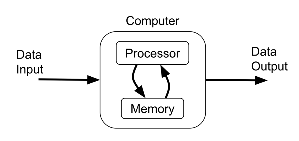
This is called the stored-program concept and when it was demonstrated in the late 1940’s, it ushered in the modern era of computing. Prior to this, computing devices could only be programmed by physically altering their electrical circuits. This model makes it possible to program a computer by loading it with a set of instructions as data input from a device like a disk or a keyboard.
After a program has been loaded or stored into the computer’s memory, it can be run. The processor runs it by reading a single instruction from memory, carrying it out by manipulating data somewhere in memory, and then moving on to the next instruction in the sequence. This cycle goes on and on until the program reaches an end. This is called the fetch-execute cycle and it is the heart of the computational engine; in car terms, it’s akin to the combustion cycle. The whole situation relies fundamentally on the abilities to electronically store and manipulate data. We can see the baby steps of these abilities in action by taking a look at a couple of interesting circuits.
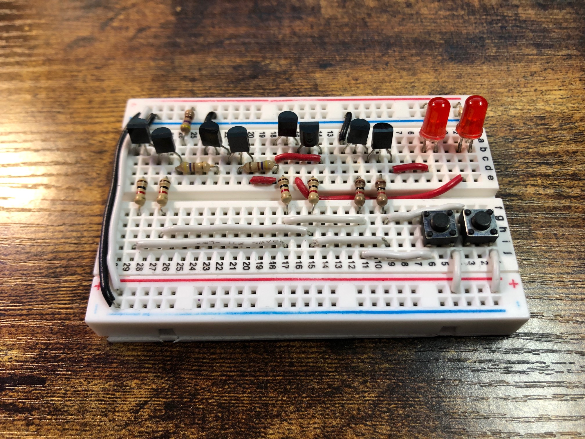
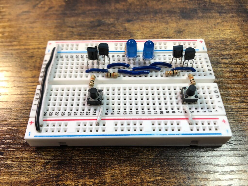
This kind of circuit is called an adder. Computers use these circuits to perform addition and, in some creative ways, other basic arithmetic functions. This adder in particular is a half adder, the simplest type of adder. It can add two single binary-digit (bit) numbers together. Let’s see what that looks like.
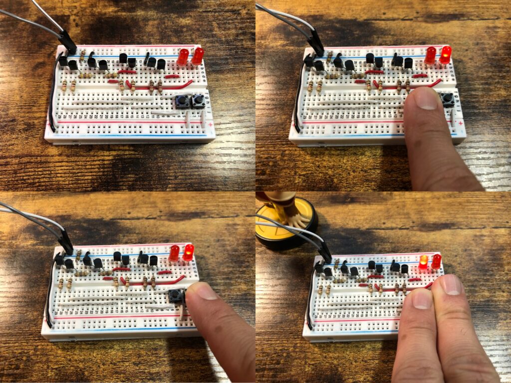
Top Left: Once connected to power, calculation is constantly occurring. Each button controls input to one of the single bit addends. When neither button is pressed down, the adder is calculating 0+0 and displaying “00” as a result in the form of two unilluminated LED’s.
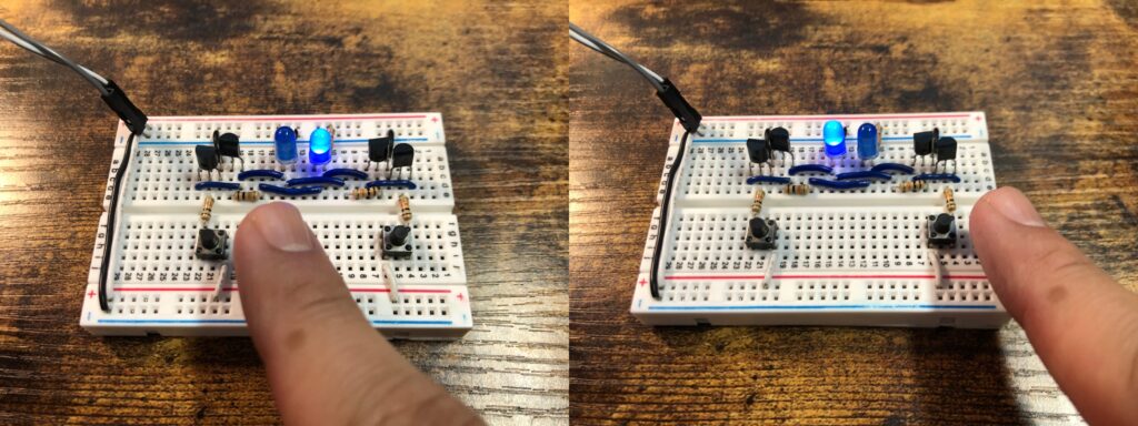
Top Right: Pressing and holding the right button changes the input of the right addend to 1, telling the adder to complete 1+0 which it displays as “01”.
Bottom Left: Likewise, pressing and holding the left button is like telling the adder to complete 0+1, which it displays as “01”.
Bottom Right: Pressing and holding both buttons changes the input of both addends to 1, forcing the circuit to deal with the problem of 1+1. The output shown on the LEDs is “10”, 2 in binary numeral system.
The output is represented by a row of 2 bits, a 2-bit number. 2 bits can together express 4 unique values. In this case we use them to represent whole numbers starting from 0 as “00” all the way up to 3 as “11”. Although in the case of a half adder, the sum can only get as high as 2 as “10”.
You might wonder why this circuit is called a half adder. A full adder is a slightly more complicated circuit that takes in 3 single bit inputs and so can reach sums all the way up to 3. As we’ll see later, full adders can be chained together to create higher order adders that can perform addition on larger numbers.
This type of circuit is called a latch. Computers can use circuits like these to store information in memory. This latch in particular is a set-reset latch, the simplest type you can build. It can latch onto a single bit of data.
When the circuit is plugged into power, one of the two LEDs at random will light up and stay lit. We don’t care which LED it is that initially lights up just as we don’t care about any random bits that might go on in our memory chips at the moment we turn on our computers. It’s all the same to us, blank slate until we write something to it.
When the left button is pressed, no need to keep the button held down, the right LED goes on and stays on and the left LED turns off and stays off. When the right button is pressed, the left LED goes on and stays on and the right LED turns off and stays off. The memory of a single bit of data is preserved with the touch of a button. Although there are two LEDs, it is only one bit of data that is stored in this circuit since the two data signals are always opposite of one another
You might wonder what happens when both buttons are pressed down at the same time. As long as both buttons are held down, both LEDs will turn off. This input state is is considered invalid however because it breaks the inverse relationship of the outputs and scrambles the data the memory into an indeterminate state, just like plugging and unplugging the circuit from power.
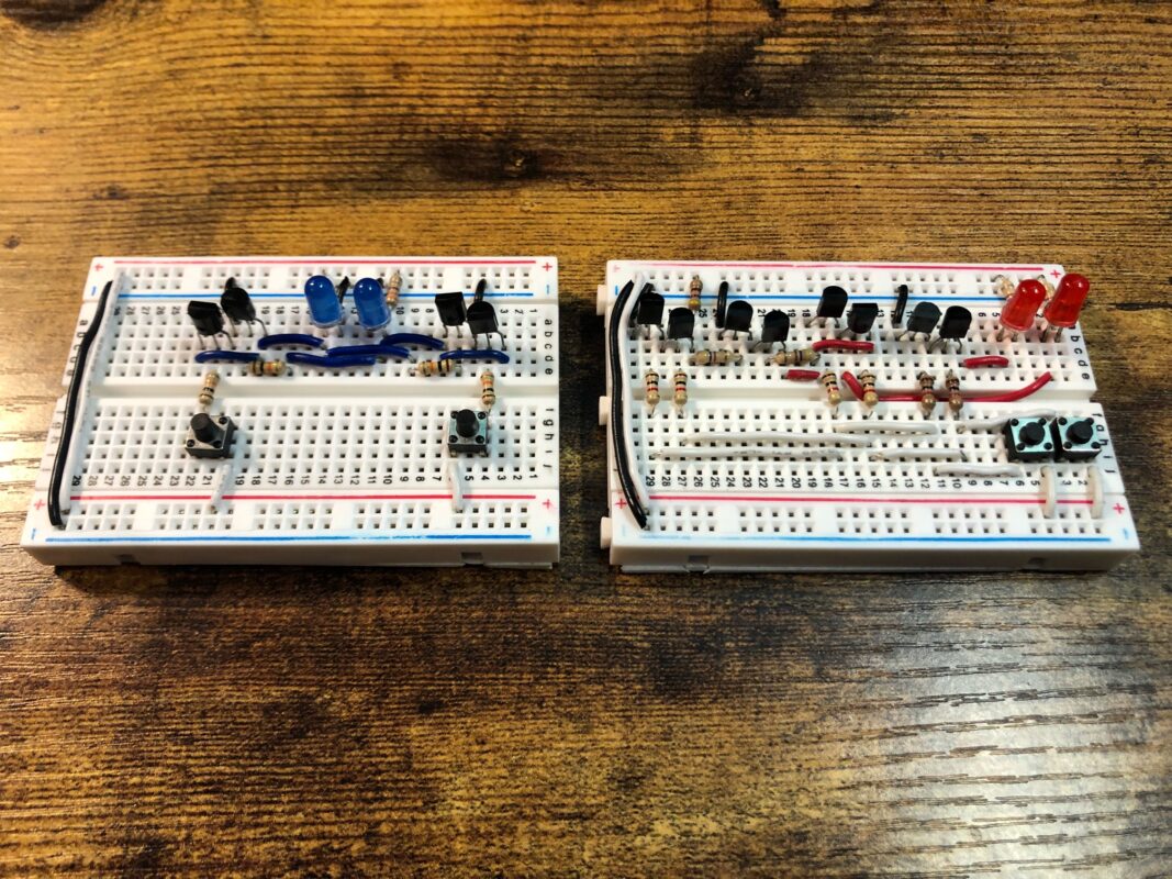
With these two circuits we can see the core logical functions of a computer being performed at the barest possible level. We can manipulate data by adding numbers together and we can store data by setting bits. We are doing this not with computer programs but directly with transistors, those three pronged black components decorating the circuits. Resisters play a role in protecting the circuitry from self harm, as we’ll talk about later, but it’s the transistor that is is the primary actor in making these simple functions possible. So what does it do? To answer that, we need to talk about switches.
Switches
A switch is really any device or method of altering a path of some kind of physical motion or flow. You can think of a railroad switch which changes the path of a train by selecting a track at a junction point. Today the term almost ubiquitously is used in the context of electrical circuits, that is in changing the path of an electrical current.
The first practical, widespread use of electrical circuitry was the telegraph. Decades before light bulb was even invented, people were utilizing electricity to communicate quickly through long distances. Using a telegraph, you could send electric pulses down a long wire to be received and interpreted to a person the other end. Let’s see how that worked. [Some of the following diagrams are taken from Code: The Hidden Language of Computer Hardware and Software by Charles Petzold]
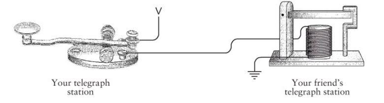
If you wanted to transmit a message to your friend, you would sit at your desk and start tapping down on your telegraph’s key, a button like switch that completes an electrical circuit between you and your friend. You would tap it down quickly to create a short pulse, called a dot, and and hold it down longer to create a long pulse, called a dash.
On the other end, your friend would receive the signal by sitting at his desk and listening to the sounds that her telegraph sounder would make. The sounder sounds because the electrical wire is wrapped around in a coil and sits close to a iron lever. You might remember from high school physics that when an electrical current is made to circle around many times as in a coil, it creates a strong magnetic field. That magnetic field attracts the iron lever which then makes a click sound when it bangs down against its frame then a clack sound when the magnet is shut off as it moves back up to its original position. The click-clack sound is similar to the sound a computer mouse or retractable pen makes. Your friend, with some training, can distinguish dots and dashes by the length of time between the clicks and clacks and then translate sequences of dots and dashes to letters of the alphabet.
It was a great utility for its time, but it had a problem. Long stretches of wire impart large resistance to their electric currents. This means that if you and your friend were too far apart without a high enough voltage source, the current would be too weak to make the sounder operate correctly. Most telegraph signals could only travel a few hundred miles at best. There needed to be a way to give the signals an extra push halfway down the line.
You could imagine a solution where a man sits in the middle. He would be hooked in with a sounder connected back to your key so that he can hear the messages that you send. On the other side of his desk, he would have his own key connecting a local voltage source to your friend’s sounder. He would listen to your messages and relay them down the line to your friend for you. This setup could work but the better solution would be to have a way to automate the process.
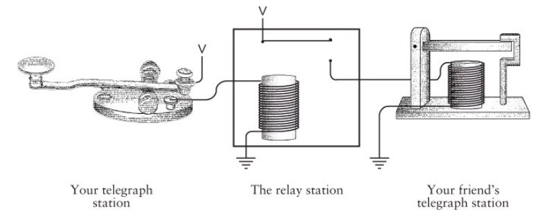
That could be done with a device called, appropriately enough, a relay. It works much like the sounder does with a coil to create an electromagnet. The difference is that the magnet here is used to attract a iron lever not to produce sounds but instead to complete a circuit from the new voltage source to your friend’s sounder. It’s recreating the same motion with the same timing as you would be making with your key. It’s really just a switch, but it’s a special kind of switch. It’s a switch that can be operated by the same type of physical phenomena that the switch itself controls, electrical current in this case. This sort of feedback-operated property allows these kinds of switches to be connected together in various ways and have chain reactions of switchings flow through them. And that makes them remarkably useful in the realm of automation.
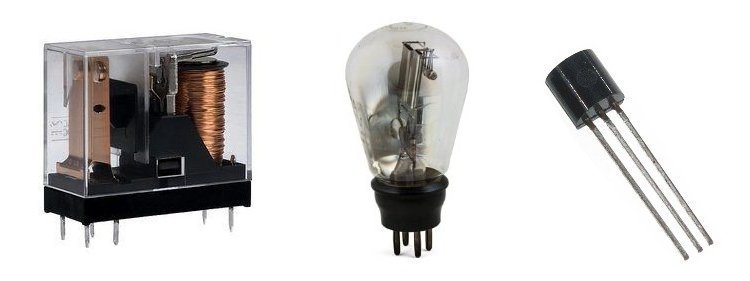
The 20th century saw three such electrically-operated electrical-switching technologies in widespread use, pictured here. The first was the relay. In case you are wondering, the wire making up the coil of the electromagnet is insulated from itself using a thin transparent film. So the copper wire, although visible, is not actually touching itself and the coil can still function as a strong electromagnet. Since relays work by moving a piece of metal, i.e. the lever, they are said to have moving parts and are categorized as electromechanical devices. Relays were first used as described above, to amplify telegram signals as they traveled across states, countries, and continents. The first generation of electric computers were built using these switching devices.
Later when the telephone was invented, a similar problem arose where the electric signal created from the microphone would arrive too weak when traveled over a long distance and the listener on the other end could barely hear it. Relays could not help here because these signals were analog (of varying voltage) rather than digital (simple on/off). The vacuum tube, whose origins trace back to electrical experiments carried out by Thomas Edison on his light bulb, was found to be able to amplify these signals in a way that was similar to how the relay worked on telegram signals. The mass production of vacuum tubes completely blew up the telephone and radio industries. Later it was shown that vacuum tubes could also be used to amplify digital signals just as relays had already been doing. Thus they were used to build the second generation of electric computers. They worked much better than relays for this purpose because they were completely electric in their switching mechanism rather than electromechanical which meant they could switch many times faster than relays, leading to faster computers.
Finally the transistor came along. The transistor performs the same function as the vacuum tube, only with many practical benefits due to form factor. While a vacuum tube uses an evacuated chamber to function, a transistor is made with a 100% solid material called a semiconductor and so is referred to as a solid state electronic device. Because of this, they can be made much smaller and work much more efficiently. One of their very first uses was to miniaturize radios which before had been built with vacuum tubes and so were typically the size of milk crates but were now suddenly small enough to fit in a pocket. They could also switch even faster than vacuum tubes, leading to faster computers still.
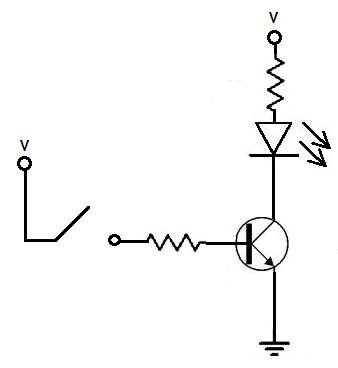
Pictured here a diagram of a simple circuit showing a transistor at work. The diagram depicts a transistor (the encircled piece), an LED (the upside down triangle), two resistors (the zigzags) and finally a manual switch. In these kinds of circuits resisters serve two purposes – limit the current going into other components so that they don’t burn out and prevent short circuits which is when the voltage source becomes directly connected to ground.
While the manual switch is the off position, current will not flow into the middle leg of the transistor (called the base) and through to the lower leg (called the emitter) to ground. This will cause the transistor to be off and behave with high resistance from its top leg (called the collector) to its emitter, blocking current from flowing through. Since current is blocked through that pathway, the LED will be off. When the manual switch is in the on position, current will flow through the base, causing the transistor to be on and behave with high conductivity from the collector to the emitter, completing the circuit which then lights up the LED. The story is functionally the same as that of the relay used to extend the reach of the telegram signal.
Logically speaking, this circuit expresses a 1-1 mapping of signals between the manual switch and the electrically operated switch. That’s good if you just want to amplify a signal, not so useful to perform any kind of data processing. But if we play around with the circuitry using just these basic components, we can express any logical mapping we can imagine.
Gates and Tables
Any automata, machinery, or system that you build will have its functionality rooted in logic. Mathematics as a field of study is nothing but applied logic, similar to how the study of physics can be seen as application of math. While math and physics are formally taught to most people in school, logic is not necessarily, leading to a disconnect. Fortunately only some basic, fairly intuitive logic is necessary to get off the ground. Consider a simple example:
(engine pushes) = (is on) AND (in drive) AND (pedal pressed)
An engine will push the car if it’s on, in drive, and the pedal is pressed. The statements in parentheses are called propositions. Propositions can be connected to form compound propositions using logical connectives like AND or OR. Finally, a proposition acts like a variable that can take on one of two values: true or false. This equation describes the exact condition in which the engine will push the car. Of course in the real world, there may be many more variables to consider but this simple example demonstrates how propositional logic can be used to formally describe a function.
Since automation is derived from logic, the first step in building a machine that can automate the processing of data signals is to build physical devices that can mimic the function of logical connectives. This is where switches shine. [Some of the following diagrams are taken from HyperPhysics at Georgia State University]
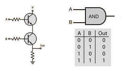
If we connect two transistors in series like this, then we will have constructed an electric device that acts like an AND connective. Only when it is true (represented by the number 1 but may also be referred to as high) that voltage is applied to the lines A and B will it be true that current is allowed to pass through the Out line. We can call the device an AND gate and give it the pictured symbol which we can use later to construct logic diagrams. Below the symbol is its truth table. Truth tables are a type of lookup table like the multiplication tables you were forced to memorize in elementary school. Lookup tables explicitly map the inputs and outputs of a function for quick lookup and actually turn out to be an important aspect of how computers process data, as you’ll see. Bringing it back to gates though, there are a number of other 2-input logic gates we can build using just two transistors.
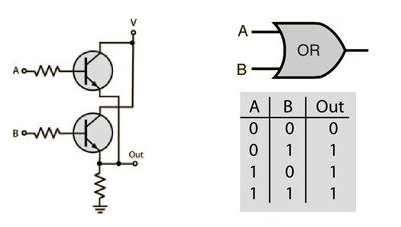
The OR gate will only output high if either A or B is high.
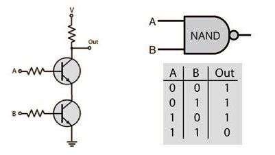
The NAND gate is a negated AND gate. For every output of an AND gate, a NAND gate will output the opposite value.
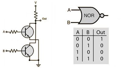
Similarly to the NAND gate, the NOR gate is a negated OR gate.
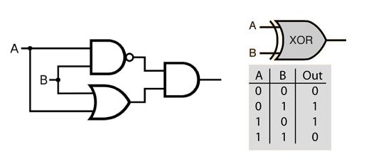
We can use gates in logic diagrams to build other gates. The XOR gate, for exclusive-OR, is similar to the OR gate but it will only output high if only one of its inputs is high. A simple way to construct an XOR gate is with a NAND, OR, and AND in the following configuration.
It can actually be shown that any truth table of any number of inputs to outputs whatsoever can be constructed using either just 2-input NAND gates or just 2-input NOR gates. These two singleton sets of gates are the minimal functionally complete sets. Since all of the logic of a computer is expressed by truth tables, this means you can build all of the logic of a computer using just one of those types of gates. In practice though, using a variety of logic gates is more efficient and easier to follow along.
Now that we have the standard set of logic gates in our tool bag, we can construct higher order logic components which do in fact become the building blocks of the computer. The following is a logic diagram and corresponding truth table for a half adder. [Some of the following diagrams are taken from youtube.com/c/ComputerScienceLessons]

The half adder presented earlier is built just like this, using an AND gate built with two transistors and an XOR gate composed of the aforementioned trio of gates and using six transistors. The S output is called the sum output and the C output is called the carry output. I mentioned before that a full adder takes in a third input. This input is called the carry in. Full adders can be chained together from carry in to carry out like so
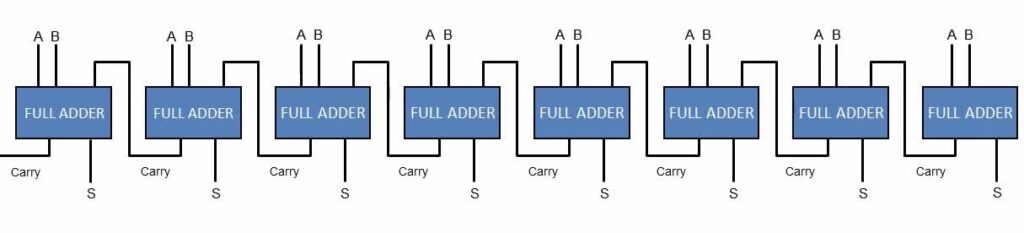
On this 8-bit adder, 1+1 would look like this:
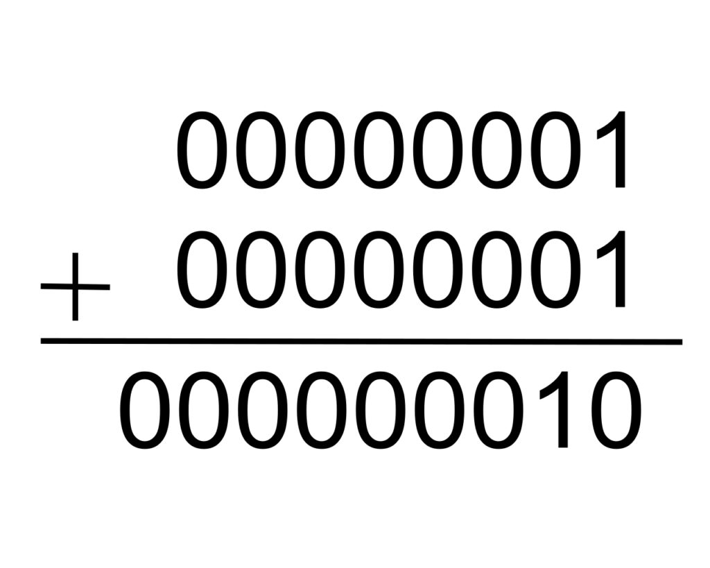
That’s two 8-bit strings as input and one and 9-bit string as output, 8 sum bits and a final carry bit. That final carry bit in the sum can be used as a flag bit, a way of telling a program, “hey, the sum of the two numbers you just tried to add is too big to fit in 8 bits. Do you want to do something about that?”
8-bit strings can represent 256 unique values, in this case the numerical values 0 to 255. You can imagine what the huge truth table would look like for an 8-bit adder, showing all possible combinations of input addends to output sums.
An adder is an example of combinational logic, the basis of data manipulation. Combinational logic is the term used to describe using logic gates to build functions of time independent input to output. Another type of logic called sequential logic describes logic systems that are time dependent. That is to say that their current output values can depend on previous sequences of input values. This is the kind of logic used to build latches and other memory chips. Take a look at the diagram and truth table for the set-reset latch.
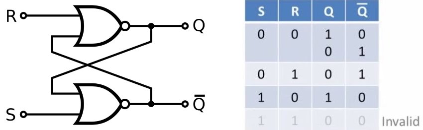
This setup is built using two NOR gates, so it only uses four transistors. Contrast that with the half adder which uses eight. Although it may seem simpler than the half adder, this design can really throw you for a loop, a feedback loop.
Feedback loops are a core aspect of systems analysis. This is when output of one part of a system is set to circle back into another part of the system. You can see by the diagram that the output of both NOR gates circle back into each other. This is how the system is able to set memory and it’s best describe by a working example. Note one input is labeled as set and the other is labeled as reset. The circuit is completely symmetrical so it doesn’t matter which is called which, as long as the set corresponds to the Q output and the reset to not-Q output. The following is a step by step sequence of actions that occur from a stable state where Q is high, to a destabilization caused by momentarily high input into the reset line, to the next stable state.
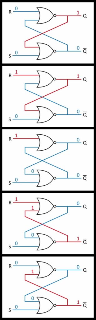
As you can see, the high output from one NOR gate will always cause the other NOR gate to output low. That may sound like a sad story but it’s great for data memory storage. You can picture a row of 8 set-reset latches in a row. By setting a bit at each latch, you will have saved 8 bits in memory, one byte. The Q is regarded as the data while the not-Q is ignored.
And that, my friends, is how logic makes computers. What I’ve described here are the two principals of computer logic, namely data manipulation through combinatorial logic and data storage through sequential logic. In a follow up post I will write a bit more on how a basic computing system reads and executes its instructions by looking at an example of an actual 8-bit computer.